iStingor Tone Lab
True Bypass vs Buffered Bypass
The Technical Difference in Guitar Pedals
iStingor Tone Lab
The Technical Difference in Guitar Pedals
In guitar pedals, True Bypass and Buffered Bypass are often oversimplified as “one is pure, the other colors the tone.” That is not technically accurate.
The real issue is not simply whether the signal passes through a circuit. It is about impedance relationships, cable capacitance, load-driving ability, frequency response, headroom, switching noise, and overall noise level across the entire signal chain. True Bypass answers the question of whether the circuit is bypassed when the pedal is off. Buffered Bypass answers the question of whether a high-impedance guitar signal can drive the following cables and devices reliably.
So the right way to judge a bypass system is not by its name alone, but by how it works inside the complete rig.
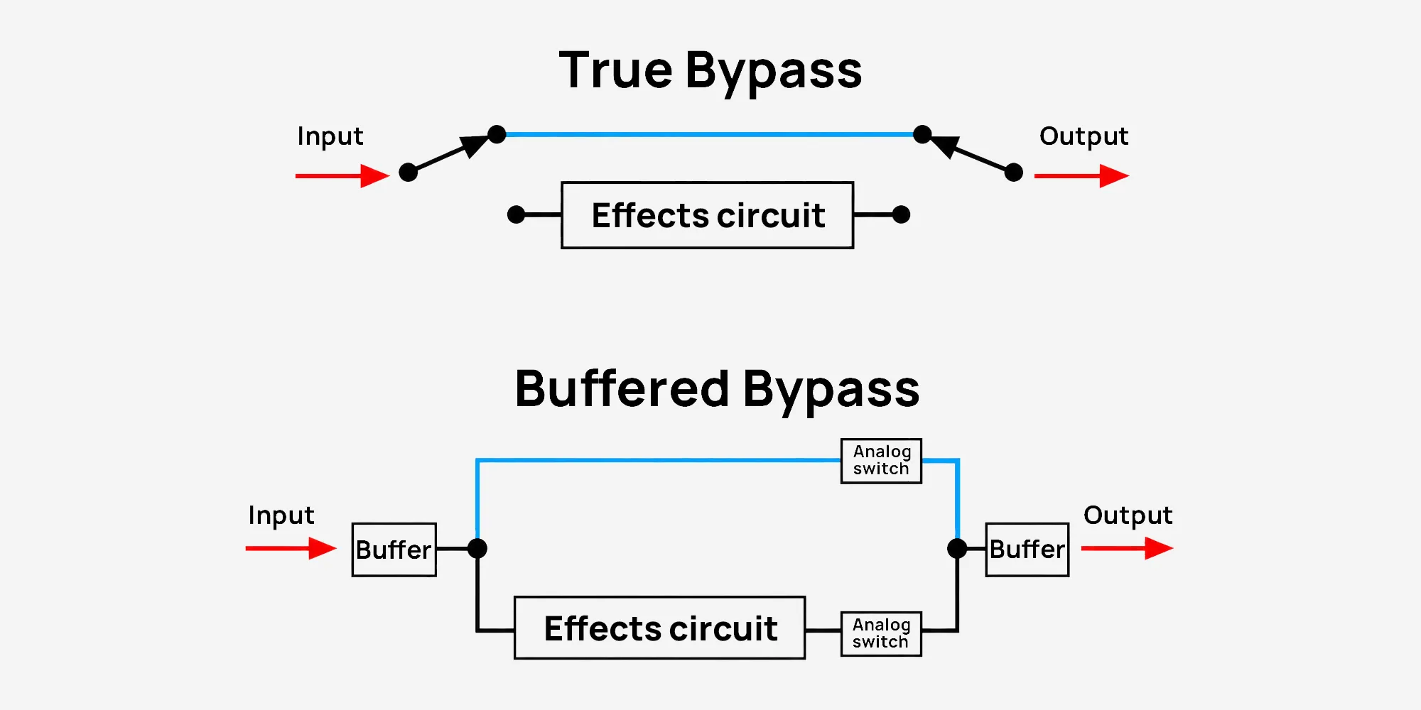
True Bypass means that when the pedal is off, the signal is routed directly from input to output through a mechanical switch, theoretically without passing through the pedal’s active circuit. Its advantage is straightforward: in bypass mode, the signal does not go through a buffer, amplifier, or tone-shaping circuit.
Buffered Bypass means that when the pedal is off, the signal still passes through a buffer stage. An ideal buffer usually has:
In simple terms, True Bypass focuses on bypassing the circuit when the pedal is off. Buffered Bypass focuses on passing the signal through an impedance-conversion stage even when the pedal is off. They are not about one being absolutely superior to the other; they solve different problems.
A guitar pickup is not an ideal voltage source. It has output impedance. The next device is also not an infinite input impedance; it acts as a load. The most basic voltage transfer can be described by the voltage divider equation:
Where:
If we simplify the guitar’s effective output impedance as 100kΩ, and the next device has 1MΩ input impedance:
In decibels:
This is a small loss, which is why a 1MΩ input is usually considered a reasonable high-impedance input.
But if the next stage has only 220kΩ input impedance:
That is already a noticeable level loss. More importantly, in a real pickup system, impedance changes also affect the resonant behavior formed by the pickup and cable capacitance, which can change both high-frequency response and playing feel.
Therefore, the first value of a buffer is not to “beautify the tone,” but to create a more appropriate impedance relationship.
True Bypass does not actively cut high frequencies by itself. However, when multiple true-bypass pedals are connected in series, the bypassed system can effectively make the guitar see longer cable length and more capacitive load. A cable is not an ideal wire; it has capacitance. Source impedance and cable capacitance form a low-pass filter:
Where:
Assume the total cable capacitance is 1000pF, and the source impedance is 100kΩ:
This is a simplified RC model. It does not mean that real guitar treble suddenly disappears above 1.6kHz. A real pickup also includes inductance, winding resistance, and a resonant peak. But this calculation clearly shows one fact:
High source impedance plus large cable capacitance can significantly change high-frequency response.
If a high-quality buffer lowers the output impedance to 1kΩ, with the same 1000pF load:
This cutoff frequency is far above the main range of the guitar and human hearing. In other words, the key role of a buffer is to lower output impedance so that the following cable capacitance can no longer pull down the high end so easily.
If we want the system to remain reasonably flat before 20kHz, we can rearrange the low-pass filter equation to estimate the maximum acceptable output impedance:
Assume the total cable capacitance is still 1000pF, and we want the cutoff frequency to stay above 20kHz:
This means that to drive a 1000pF load reliably up to 20kHz, the output impedance should preferably be below about 8kΩ. A high-quality buffer typically has an output impedance far below this range, which is why it is better suited for large pedalboards, long cables, and complex live rigs.
This also explains why an all-true-bypass pedalboard can sound excellent with short cables, but may start to sound darker, softer, or less responsive as cable length and pedal count increase. The problem is not the idea of True Bypass itself; it is the combination of total system capacitance and a high-impedance signal.
The advantage of True Bypass is clear: when the pedal is off, the signal does not pass through an active circuit. In a simple rig with short cables and only a few pedals, this approach is direct and reliable.
True Bypass is often suitable when:
Some vintage fuzz circuits in particular need to “see” the pickup’s impedance and inductive behavior directly. If a buffer is placed before them, their cleanup behavior, dynamic response, and treble structure may change.
However, True Bypass does not automatically mean “problem-free.” If the circuit is not designed properly, True Bypass switching can still produce noticeable Pop Noise or Switching Pop.
Common causes include:
A simple RC discharge model can help explain this:
If the coupling capacitor is 100nF and the pull-down resistor is 1MΩ:
After about 5τ, the capacitor voltage is usually close to stable:
This shows that pull-down resistors, coupling capacitor discharge paths, and DC reference points are not minor details. They are important design factors that affect switching noise.
A good True Bypass design is therefore not just a switch that “hard-routes” the signal around the circuit. It also needs proper DC management at the input and output, clear discharge paths for coupling capacitors, stable ground reference, and anti-pop measures. Otherwise, even a true-bypass pedal can produce a loud “pop” when switched, which can be distracting in performance or live use.
Buffered Bypass is better suited to solving signal-transmission problems in larger systems. Its goal is not to “change the tone,” but to deliver the signal more reliably to the next stage.
Buffered Bypass is often useful when:
Mathematically, the value of a buffer can be summarized as:
That means high input impedance and low output impedance.
High input impedance reduces pickup loading. Low output impedance reduces high-frequency loss caused by cable capacitance. A well-designed Buffered Bypass should not be dismissed as “tone coloration.” It should be understood as impedance conversion and signal-integrity management.
In a long-cable system, a buffer is not adding some mysterious “brightness.” It is helping preserve the high frequencies that cable capacitance would otherwise reduce.
Buffered Bypass does not automatically mean high quality. A poor buffer can certainly cause tone problems. Common causes include:
Headroom is especially important. Many 9V pedals use a virtual ground around 4.5V, and the audio signal swings above and below that center point. In theory, the maximum swing is limited by the 9V supply. In real circuits, the usable swing is further reduced by op-amp, transistor, or biasing limitations.
Assume a buffer has an actual usable output swing of about 3Vpp. For a sine wave, the RMS value is:
Converted to dBu:
If a front-end boost, active pickups, or high-output humbuckers exceed this range, the buffer may clip earlier than expected. In that case, even if it is called Buffered Bypass, it is not truly transparent.
The quality of Buffered Bypass depends on design details: input impedance, output impedance, frequency response, noise, power supply, and headroom. The name alone does not guarantee the sound.
True Bypass and Buffered Bypass are not about one being absolutely superior and the other being inferior. They are suitable for different systems.
A simple way to judge:
A practical signal-chain concept could be:
Guitar → Impedance-sensitive Fuzz / Vintage Wah → High-quality Buffer or Buffered Bypass Pedal → Other Effects → Long Cable → Amplifier
A truly professional bypass design is not about chasing a marketing term. It is about maintaining the right impedance relationship, stable frequency response, sufficient headroom, clean switching behavior, and controlled noise level inside a real signal chain.
True Bypass solves the question: “Does the signal bypass the circuit when the pedal is off?” Buffered Bypass solves the question: “Can the signal reliably drive the following load?”
That is the real technical difference between them.