iStingor Tone Lab
Guitar Tone Basics: Tone Capacitors
A tone capacitor shapes guitar tone by reducing treble. Different capacitor values change how the tone control responds, making the sound brighter, warmer, or darker.
iStingor Tone Lab
A tone capacitor shapes guitar tone by reducing treble. Different capacitor values change how the tone control responds, making the sound brighter, warmer, or darker.
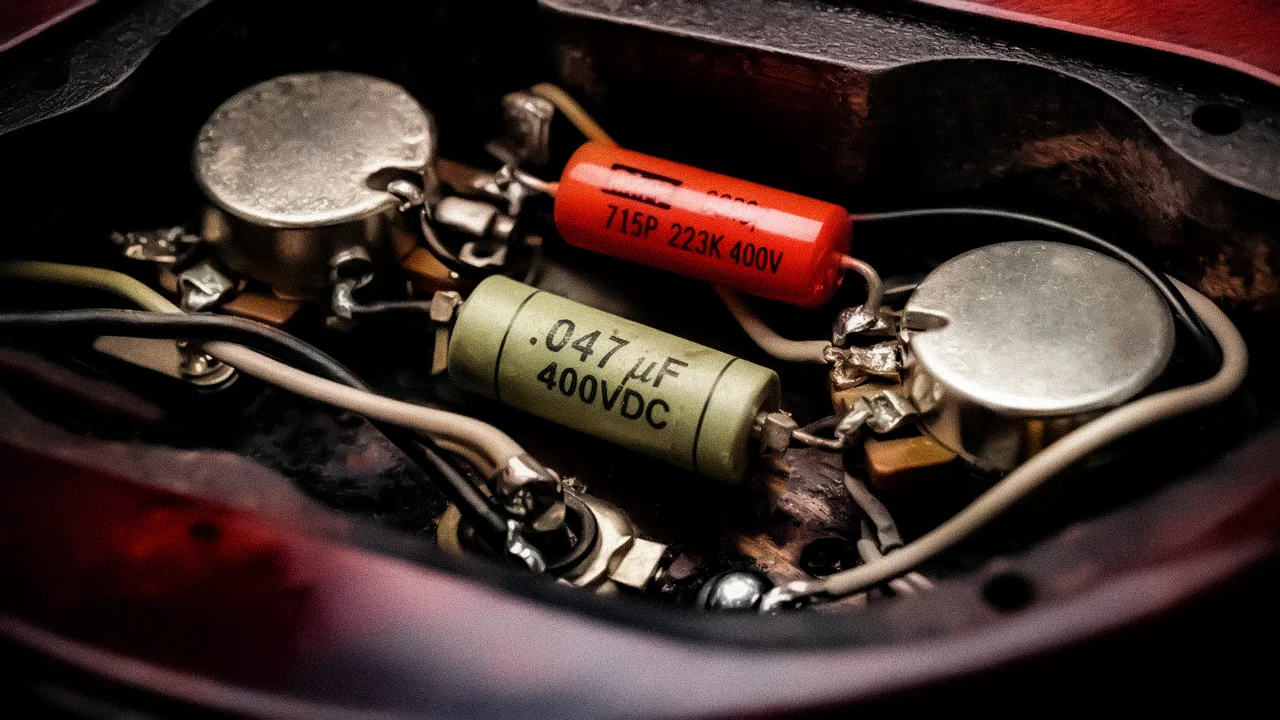
Many guitar players spend a lot of time comparing pickups, strings, pedals, and amplifiers, but often overlook one very small component inside the guitar circuit: the tone capacitor.
It may look simple and inexpensive, but it affects how the tone control shapes the sound. When you roll down the tone knob, the capacitor helps determine how much treble is reduced, how gradually the sound changes, and how dark the final tone becomes.
In simple terms, in a typical passive electric guitar, the tone circuit can be understood as a potentiometer-controlled high-frequency bypass network. It produces an effect similar to low-pass filtering, but the real response is also affected by the pickup, potentiometers, cable capacitance, and the input impedance of the next device.
The core function of a tone capacitor is not to “add bass.” Instead, it allows part of the high-frequency signal to pass through the capacitor path to ground, reducing treble and making the sound feel darker, rounder, and smoother.
This perceived “thickness” does not come from actively boosting low frequencies. It happens because the reduced high-frequency content makes the low and midrange content feel more prominent.
A tone capacitor does not actively boost any frequency range. What it really does is reduce part of the high-frequency content.
When the tone knob is fully open, the impedance of the tone capacitor path is relatively high, so its audible effect is usually small, but not always completely zero. Unless a no-load tone pot is used, the tone capacitor path can still remain slightly involved in the circuit.
As you roll the tone knob down, the effective impedance of the capacitor path becomes lower. More high-frequency content is bypassed to ground, and the sound gradually becomes rounder, thicker, and darker.
The tone capacitor mainly affects:
This is why the same guitar can feel noticeably different after changing the tone capacitor value.
From an electronics perspective, the guitar tone control is not a mysterious component. It is a passive tone-shaping network made from a potentiometer and a capacitor.
In many passive electric guitar circuits, the tone potentiometer and tone capacitor form a path to ground:
Signal node → Tone potentiometer → Tone capacitor → Ground
A capacitor presents different impedance at different frequencies. The higher the frequency, the lower the capacitive reactance, so high frequencies can pass through the capacitor path to ground more easily. The lower the frequency, the higher the capacitive reactance, so low frequencies are less likely to be bypassed.
The absolute value of capacitive reactance is:
Where:
|Xc| = absolute value of capacitive reactance, in ohms
f = frequency, in Hz
C = capacitance, in farads
This formula shows one key principle: the same capacitor presents higher impedance at low frequencies and lower impedance at high frequencies.
That is why a tone capacitor does not add low end. It makes part of the high-frequency signal easier to send to ground, which makes the sound feel darker, rounder, and smoother.
The values in the table below are not based on subjective experience or brand descriptions. They are calculated using the standard capacitive reactance formula |Xc| = 1 / (2πfC). The table shows how different capacitor values behave at different frequencies in an ideal capacitor model.
It is important to note that this table only shows the reactance of the capacitor itself. It should not be treated as the complete frequency response of a guitar. A real guitar circuit is also affected by pickup inductance, coil resistance, potentiometer values, cable capacitance, and the input impedance of the next device.
| Frequency | 0.015 µF | 0.022 µF | 0.047 µF | 0.1 µF |
|---|---|---|---|---|
| 1 kHz | 10.61 kΩ | 7.23 kΩ | 3.39 kΩ | 1.59 kΩ |
| 2 kHz | 5.31 kΩ | 3.62 kΩ | 1.69 kΩ | 0.796 kΩ |
| 5 kHz | 2.12 kΩ | 1.45 kΩ | 0.677 kΩ | 0.318 kΩ |
| 10 kHz | 1.06 kΩ | 0.723 kΩ | 0.339 kΩ | 0.159 kΩ |
For example, 0.022 µF at 1 kHz:
C = 0.022 µF = 22 × 10⁻⁹ F
f = 1000 Hz
So the values in the table are calculated from the formula and are used to show the relationship between capacitance and frequency.
The table shows that the larger the capacitor value, the lower the reactance at the same frequency.
This means a 0.047 µF capacitor allows high frequencies to pass through the capacitor path to ground more easily than a 0.022 µF capacitor, resulting in a darker sound when the tone control is rolled down. A 0.015 µF capacitor has higher reactance, so it reduces treble more gently and keeps more brightness and clarity.
| Capacitor Value | General Character |
|---|---|
| 0.015 µF | Gentle treble softening, more clarity retained |
| 0.022 µF | Balanced and versatile, common in modern electric guitars |
| 0.047 µF | Stronger treble reduction, traditional for many single-coil guitars |
| 0.068 µF / 0.1 µF | Darker, useful for vintage or special tones |
The cutoff frequency of an ideal first-order RC low-pass filter is:
This formula is correct, but it should not be directly applied to the complete passive guitar tone circuit as if it were an isolated ideal RC filter.
A standard RC low-pass filter is usually a simplified model. A real guitar circuit is more complex and includes pickup coil inductance, pickup DC resistance, pickup parasitic capacitance, volume pot loading, tone pot position, tone capacitor, cable capacitance, and the input impedance of the next pedal or amplifier.
Therefore, in an engineering explanation, it is not appropriate to simply choose a fixed resistor value and a tone capacitor value to calculate “the cutoff frequency of the guitar tone circuit.”
A more accurate explanation is: the RC formula helps explain the general relationship between resistance, capacitance, and frequency response. But the real response of a guitar tone circuit should be understood as part of a complete RLC network formed by the pickup, pots, capacitor, cable, and load.
For tone capacitor selection, it is more useful to compare the capacitive reactance of different values at the same frequency: a larger capacitor has lower reactance at the same frequency; when the tone knob is rolled down, more treble can be bypassed to ground; the sound becomes darker and thicker more easily; and a smaller capacitor reduces treble more gently and gives a more subtle tone control.
A guitar pickup is not just a simple signal source, nor is it a pure resistance. It can be understood as an RLC system made from resistance, inductance, and parasitic capacitance.
A simplified model includes pickup DC resistance R, pickup coil inductance L, coil parasitic capacitance C, cable capacitance Ccable, volume and tone circuit loading, and the input impedance of the next device.
The pickup coil inductance interacts with the equivalent capacitance in the circuit and creates a resonant region. This resonant area often plays an important role in a guitar’s brightness, clarity, air, and pick attack.
The ideal LC resonant frequency is:
Where:
f0 = ideal resonant frequency
L = pickup inductance, in henries
C = equivalent capacitance, in farads
Assume a single-coil pickup has an inductance of about 2.5 H, and the equivalent capacitance of the cable and circuit is about 470 pF:
L = 2.5 H
C = 470 pF
Using the ideal LC formula:
f0 ≈ 4.64 kHz
The 4–5 kHz region is important for electric guitar clarity, brightness, and pick attack.
When the tone knob is rolled down, the tone capacitor becomes more strongly involved in the pickup load through a lower impedance path. This increases the effective capacitance effect and shifts the resonant region lower.
For example, in an idealized estimate, if a 2.5 H pickup forms a main resonant relationship with a 0.022 µF capacitor:
f0 ≈ 679 Hz
With a 0.047 µF capacitor:
f0 ≈ 464 Hz
This shows that when the tone capacitor is strongly involved in the circuit, it does more than just remove a little treble. It changes the resonant behavior of the pickup system, making the sound thicker, darker, and sometimes giving it a fixed-wah, nasal, or vintage jazz-like character.
However, these values are only ideal LC estimates. In a real circuit, the resonant peak is damped by pickup resistance, potentiometer loading, cable effects, and the input impedance of the next device. The peak height and Q factor can change significantly. Therefore, the actual sound should not be treated as a single frequency calculated by the ideal formula.
The tone capacitor does not work alone. It works together with the tone pot, volume pot, and pickup to determine the final frequency response.
Common passive electric guitar pot values include 250 kΩ, 500 kΩ, and 1 MΩ.
| Pot Value | Common Character |
|---|---|
| 250 kΩ | Heavier pickup loading, smoother treble, commonly used with single coils |
| 500 kΩ | More treble retained, commonly used with humbuckers |
| 1 MΩ | Brighter and more open, used in some special circuits |
For example, the same 0.022 µF tone capacitor can feel different when paired with 250 kΩ or 500 kΩ pots. A 250 kΩ pot loads the pickup more heavily and usually makes the sound smoother. A 500 kΩ pot loads the pickup less and usually preserves more high-frequency content.
Therefore, when choosing a tone capacitor, the capacitor value should not be considered alone. Pot value and pickup type also matter.
The following values are common starting points, not absolute rules. The final choice should also consider the pickup, the natural voice of the guitar, pot values, cable capacitance, and personal tone preference.
Humbuckers usually have higher output, stronger low mids, and less top-end brightness than single coils. A common starting point is 0.022 µF. This is a versatile choice. It can warm up the sound without making it too dark too quickly. If the guitar already sounds dark, or if you want a more subtle treble control, try 0.015 µF. It reduces treble more gently and keeps more clarity.
Strat and Tele-style single coils are usually brighter and more cutting. Sometimes they can sound a little sharp. A traditional starting point is 0.047 µF. This value softens treble more noticeably and makes the sound thicker and rounder. It is also useful for warmer vintage-style single-coil tones. If 0.047 µF feels too dark, try 0.022 µF. This keeps more brightness and clarity.
P90 pickups sit somewhere between single coils and humbuckers. They have an open top end, but also stronger mids and a rawer texture. Common choices are 0.022 µF or 0.033 µF. Choose 0.022 µF for a brighter and more open sound. Try 0.033 µF or 0.047 µF for a thicker and more vintage tone.
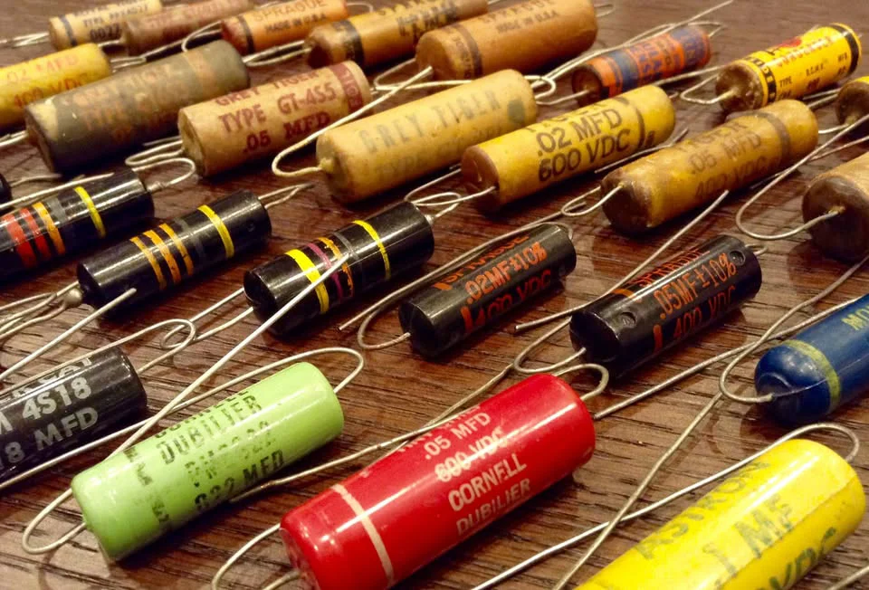
Common tone capacitor types include ceramic, polyester film, polypropylene, and paper-in-oil.
Capacitor material has long been debated among guitar players. Some believe paper-in-oil capacitors sound warmer and more vintage. Others prefer polypropylene capacitors for stability and consistency. Some believe that if the capacitance value is the same, the audible difference is not obvious.
From an engineering perspective, the more important factors in a passive guitar tone circuit are usually capacitance value, actual capacitance tolerance, actual potentiometer value, pickup inductance, cable capacitance, and overall circuit loading.
For example, a 0.022 µF capacitor with ±20% tolerance may actually measure:
0.0176 µF to 0.0264 µF
This difference in actual capacitance is often easier to hear than the difference caused by capacitor material.
A more accurate conclusion is: with the same capacitance, similar tolerance, and normal operating conditions, capacitor material is usually not the primary factor affecting the sound of a tone circuit. Actual capacitance, pot value, pickup inductance, and overall loading are often more important.
Material can be used for further fine-tuning and personal preference, but it should not be treated as the main factor that determines tone.
Many capacitors are marked with voltage ratings such as 50V, 100V, 400V, or 600V. In a passive electric guitar circuit, the signal voltage produced by the pickup is very low, so these voltage ratings are usually far higher than necessary.
In other words: voltage rating is not a major tone parameter.
When choosing a tone capacitor, it is more important to consider capacitance value, tolerance, actual measured value, physical size, and whether it fits inside the control cavity. Some high-voltage capacitors are physically large and may be harder to install inside the guitar.
Use the following as a practical starting point:
| Need | Recommended Value |
|---|---|
| Balanced, versatile, and safe starting point | 0.022 µF |
| Tone control gets muddy too quickly | 0.015 µF |
| Guitar sounds too bright or sharp | 0.047 µF |
| Warmer vintage single-coil tone | 0.047 µF |
| Humbucker with more clarity | 0.015 µF or 0.022 µF |
| Very dark, jazz, or fixed-wah character | 0.068 µF or 0.1 µF |
From an engineering standpoint, a tone capacitor can be understood this way: a tone capacitor does not add bass; it reduces treble. A larger capacitor has lower reactance at the same frequency. When the tone knob is rolled down, treble is more easily bypassed to ground through the capacitor path. The tone pot controls how strongly the capacitor participates in the circuit. The pickup, pots, capacitor, and cable form a complex RLC network. The real tonal change is not only a simple RC cutoff frequency, but also includes changes in resonant peak position and Q factor.
So instead of asking “Which capacitor is the best?”, it is more useful to ask: is my pickup naturally bright or dark? Do I want the tone control to be dramatic or subtle? Do I want the rolled-off tone to be warm or very dark? Am I using 250 kΩ or 500 kΩ pots? Will my cable and the input impedance of the next device affect the overall brightness?
The tone capacitor is one of the cheapest and easiest components to replace in a guitar, but it is also one of the most useful parts to understand.
If your guitar is too bright, try a larger capacitor value. If your tone knob gets muddy too quickly, try a smaller capacitor value. For most players, 0.022 µF is a safe starting point. A 0.047 µF capacitor is often suitable for brighter single-coil guitars, while 0.015 µF is useful when you want a more subtle and controlled treble roll-off.
A small capacitor will not completely change the personality of a guitar, but it can make the tone knob far more useful and give you a more effective way to shape your sound.
Some images in this article are sourced from publicly available online materials and are used for illustrative purposes only. If any copyright or other rights are involved, please contact us and we will address the matter promptly.